(Reference) DC Motors and Motor Driver
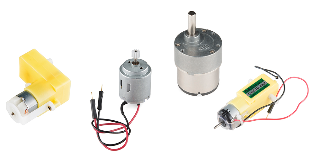
DC Motors and Motor Driver
Wiring Diagram for One Motor

Wiring Guide for One Motor
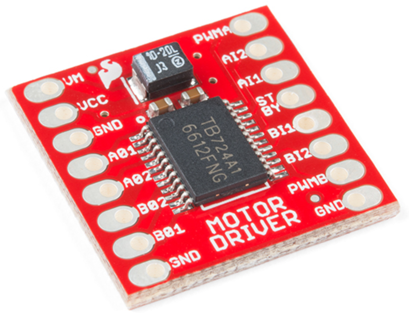
| Motor Controller | Photon 2 | DC Motor |
|---|---|---|
| PWMA | A5 (any PWM pin works) | - |
| AI2 | D4 (any GPIO pin works) | - |
| AI1 | D3 (any GPIO pin works) | - |
| AO1 | - | Motor wire (either) |
| AO2 | - | Motor wire (either) |
| VCC | 3v3 | - |
| GND | GND | - |
| VM | 3v3 | - |
| STBY | 3v3 | - |
To connect a second DC motor, connect PWMB, BI1, and BI1 to different Photon 2 pins in the same manner, and connect BO1 and BO2 to the wires on the second DC motor
Reminder: Photon 2 PWM Pins
- Only certain pins support PWM
D1(SCLorA4)A2A5MISO(D16)MOSI(D15)
Operation: Controlling the Motor Direction
- Setting the direction is done by changing the two input pins to HIGH and LOW separately
- Ex:
AI1 = HIGHandAI2 = LOWis one direction - Ex:
AI1 = LOWandAI2 = HIGHis other direction
- Ex:
- Setting them both to
LOWmeans stopping the motor - Setting them both to
HIGHcan damage the motor
Operation: Controlling the Motor Speed
- The PWM method of controlling motor speed operates on this range: [0-255]
- Typically the PWM must be somewhat greater than 0 before it starts to spin
Code
const int AIN1 = D3;
const int AIN2 = D4;
const int PWMA = A5;

void setup() {
  pinMode(AIN1, OUTPUT);
  pinMode(AIN2, OUTPUT);
  pinMode(PWMA, OUTPUT);
}

void loop() {
  // set the direction one HIGH, one LOW
  digitalWrite(AIN1, HIGH);
  digitalWrite(AIN2, LOW);
  analogWrite(PWMA, 255);    // full speed one way
  delay(1000);             	 // run for 1 second

  analogWrite(PWMA, 0); 	 // stop
  delay(1000);				 // wait for 1 second


  // change direction by switching HIGH and LOW
  digitalWrite(AIN1, LOW);
  digitalWrite(AIN2, HIGH);
  analogWrite(PWMA, 255);    // full speed opposite way
  delay(1000);				 // run for 1 second

  analogWrite(PWMA, 0);      // stop
  delay(1000);               // wait for 1 sec
}