I2C LCD Screen
I2C LCDs
LCDS Output Screens
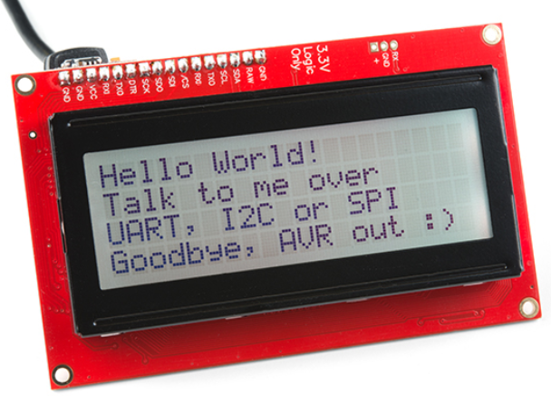
- Let’s introduce the humble LCD
Liquid Crystal Display (LCD)
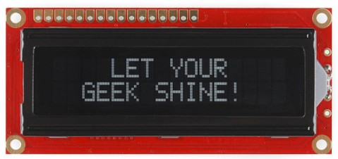
LCDs
- Output device that display text in rows and columns
- Can be use for simple graphics, but primarily for text
- Relatively cheap
- Passive, low power
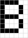
LCD Pixels
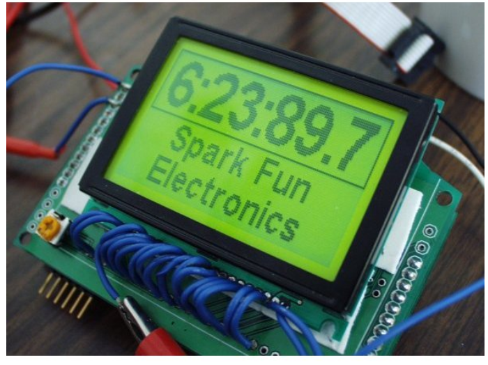
LCD Come in Many Different Sizes and Colors
Basic wiring
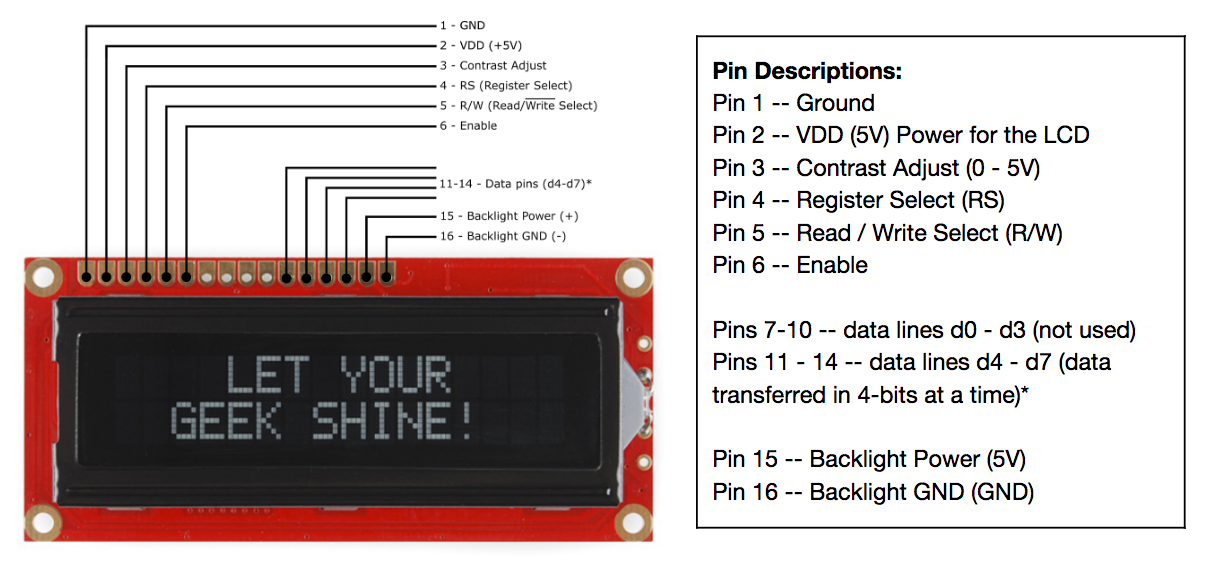
Basic Wiring
- The standard wiring of an LCD uses 16 wires (requiring 12 pins on the Photon 2)!
- The condensed wiring use 12 wires (requiring 8 pins on the Photon 2)!
- Writing code to communicate with the LCD is challenging (more on that later)
Basic wiring Condensed
Basic wiring Condensed
- 4 pins for power (2 for LCD, 2 for backlight
- 4 pins for controlling LCD
- 8 (or 4) pins for data (the text you want to display)
Parallel LCD
- There are 8 pins for data when operating in parallel
-
Let’s say you want to display the letter Q
-
The letter Q is represented on a computer by the binary string
01010001 - Each bit will be transmitted on a separate data pin
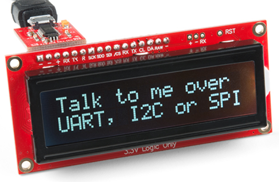
Serial LCD
- Thankfully there is a better solution!
- What is a serial communication?
- What serial protocols have used so far?
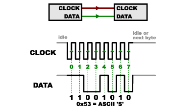
What is Synchronous Communication?
-
Data pin and clock pin
- Clock is an oscillating square wave
- On rising (low to high) or falling (high to low) edge, the receiver samples (“read”) data line
Serial, Synchronous Communication
I2C
- Inter-integrated Circuit (I2C) is a protocol to allow a central device to communicate with multiple “peripheral” chips
- Serial
- Synchronous
- Only two pins
- Data (
SDA) - Clock (
SCK)
- Data (
I2C Transmission
![]()
I2C Transmission - Part 1 Address
![]()
I2C Transmission - Part 2 Data
![]()
I2C Addresses
- Since multiple devices might be connected on the same two wires, many devices are “listening” to the communication
- Each device is given a 7-bit address to distinguish it from anyone devices
- 0000000 - 1111111 (binary)
- 0 - 127 (decimal)
- 0x0 - 0x7F (hexadecimal)
- These addresses are often fixed and specified on the hardware device
I2C vs SPI
| I2C | SPI |
|---|---|
| Uses 2 wires | Uses 4 wires; more devices means even more wires |
| Uses more power | Uses less power |
| Lower transfer speed | Higher transfer speed |
| Standardized | Multiple “versions” |
I2C Serial Backpack
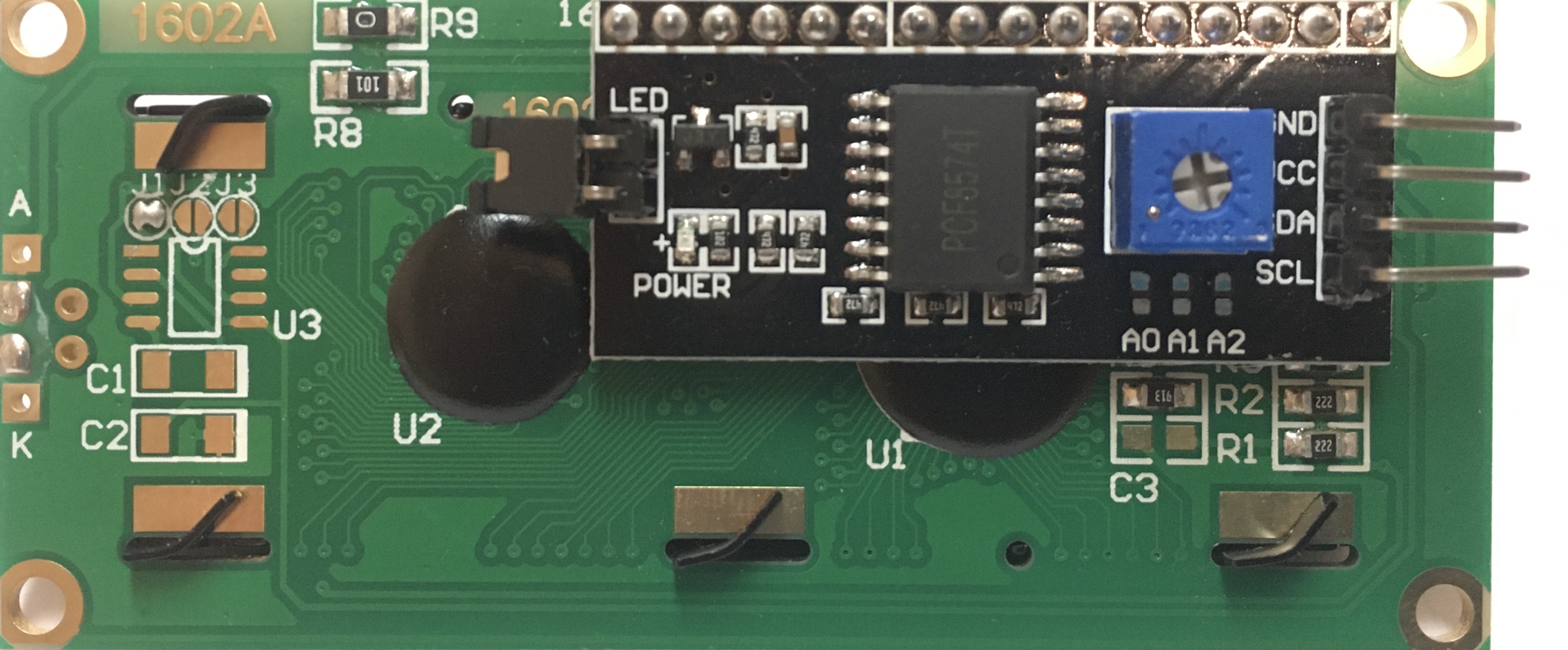
I2C Serial Backpack
- A “backpack” is a component that is added on another device
- The I2C backpack (black-colored logic board) translates the 8 pin parallel communication to 2 pin serial communication
- The blue potentiometer can be used to adjust the contrast
- Jumper on the left acts like a removeable switch to control LED backlight
Serial I2C LCD Wiring
| LCD | Photon 2 | Function | Notes |
|---|---|---|---|
| GND | GND | Ground | Ground |
| VCC | VUSB | Power | must be 5v |
| SDA | SDA | data line | |
| SCK | SCK | clock |
Special Notes
- SDA and SCL lines need pullup resistors (4.7k or 10k) to 3V3 (not VUSB)
- VCC on LCD goes to VUSB (otherwise it will be very light and hard to read)
Exercise 1
- Download project: Go to https://bit.ly/ProjectZip
- Paste the following link into the top right https://github.com/reparke/ITP348-Physical-Computing/tree/main/_exercises/week13/ultrasonic_start
- Connect I2C LCD and run example code
- Recommended library for the Photon 2:
LiquidCrystal_I2C_Spark
Exercise 2
- Connect ultrasonic range finder and displace distance to object on LCD
- Trigger: D3
- Echo: D4
- Use RGB LED to alarm: green for n