Due to variations in manufacturing and resistor tolerances
Lab 1
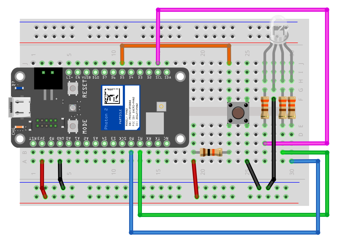
Lab 1 steps
Stage 1: Create a latch so the on-board LED turn on and stays on when the button is pressed, and the on-board LED turns off and stays off when the button is pressed again
Stage 2: Change the firmware so when the button is pressed, the following light sequence is displayed on the RGB LED
red for 1/2 sec
green for 1/2 sec
blue for 1/2 sec
orange for 1/2 sec
Stage 3: Change the firmware so when the button is pressed, a random color is show on the RGB LED
Lab 2
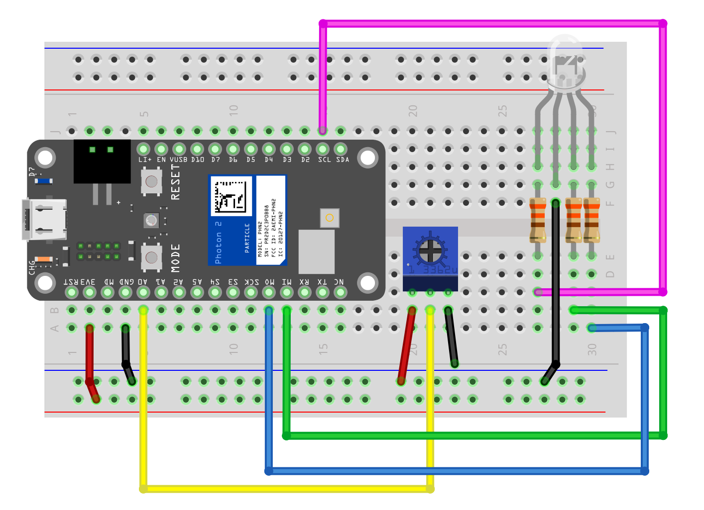
Lab 2 steps
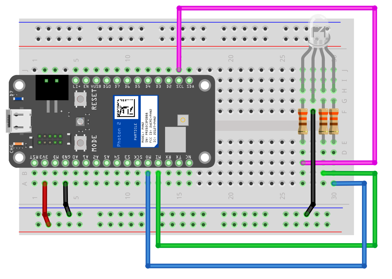
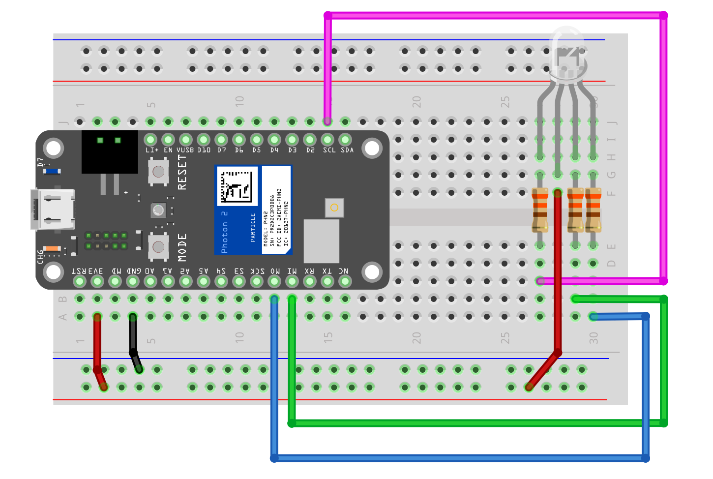
Wire an RGB LED
Wire potentiometer
Create code to allow potentiometer to control only the brightness of the red LED, and have the blue and green LED always on
Then, allow the potentiometer to control the brightness of all LEDs
Lab 3
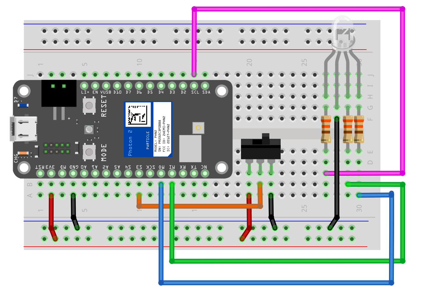
Lab 3 steps
Wire an RGB LED
When switch is to one direction, display your favorite color
When switch is other direction, display a random color
Rewrite sketch using displayColor(r, g, b) and displayRandomColor()