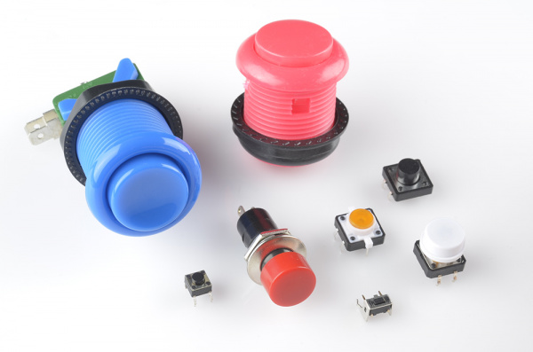

- Momentary switches that make (or break) electrical contact when pressed
- “Normally open” buttons complete a circuit when pressed (this is what is in the kit)
- “Normally closed” buttons break a circuit when pressed (we won’t use these in class)
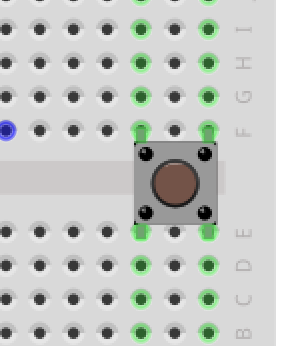
- Buttons have four pins and are designed to go across the center of the breadboard
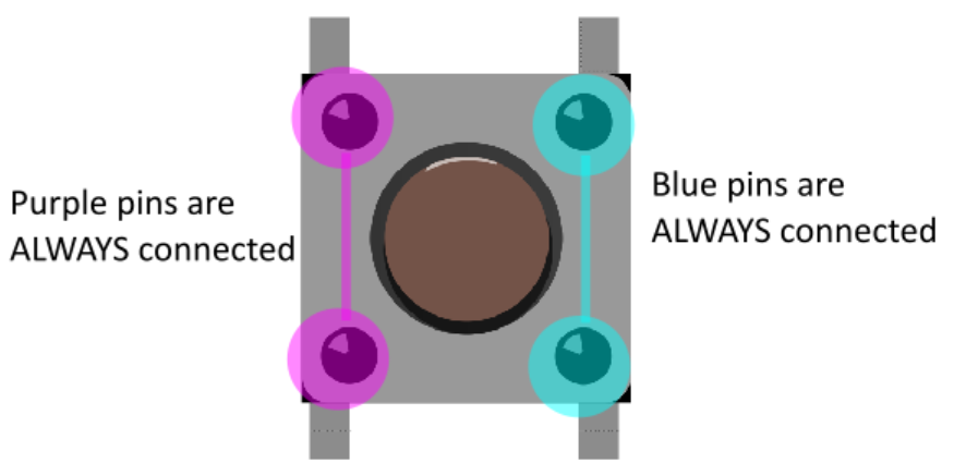
- In the picture, each set of pins “vertically across” from each other are always connected (purple and blue)
- Each set of pins “horizontally next to” each other are not connected until the button is presed
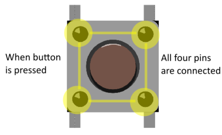
- When button is pressed, all four pins are connected (yellow pins)
Goal
- We want to use the button to send a binary (on/off) signal
- Since this is a digital input, we can use HIGH (3.3v) and LOW (gnd)
First Version
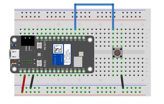
First Version - Problem
- When button is pressed, input pin is connected to gnd (LOW)
- When button is open, is it LOW or HIGH?
- When an digital input is neither exactly LOW (0v) or HIGH (3.3v), we say it is floating
- This means it is somewhere between 0-3.3v
- Should 2.4v be LOW or HIGH?
- Let’s fix this
Second Version
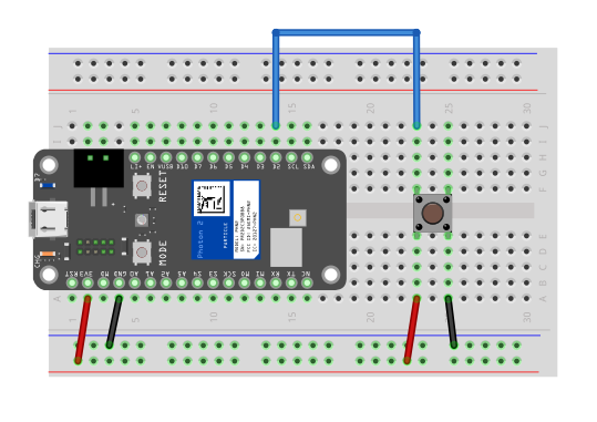
Second Version Problem
- When button is open, we have HIGH (fixed)
- When button is pressed, we connect power (3.3v) to gnd (BAD!)
Final Version
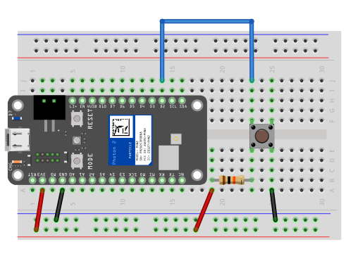
Final Version - With Pull-Up Resistor
- We use a large resistor (10k) to “pull-up” the input to 3.3v when the button is open (HIGH)
- When the button is pressed, the input goes to gnd (LOW), and we no longer have short-circuit from power to ground
IMPORTANT
- ALWAYS USE A PULL-UP RESISTOR WITH BUTTONS
- Otherwise you can damage the Photon 2 permanently
Exercise 1
- Turn LED on only while button pressed
- Toggle LED on and off after each time button is pressed
- Connect 3 LEDs (
D3, D4, D5) and turn all on and off at once
- Then turn lights on and off in a sequence (e.g. (3 states)
Exercise 2
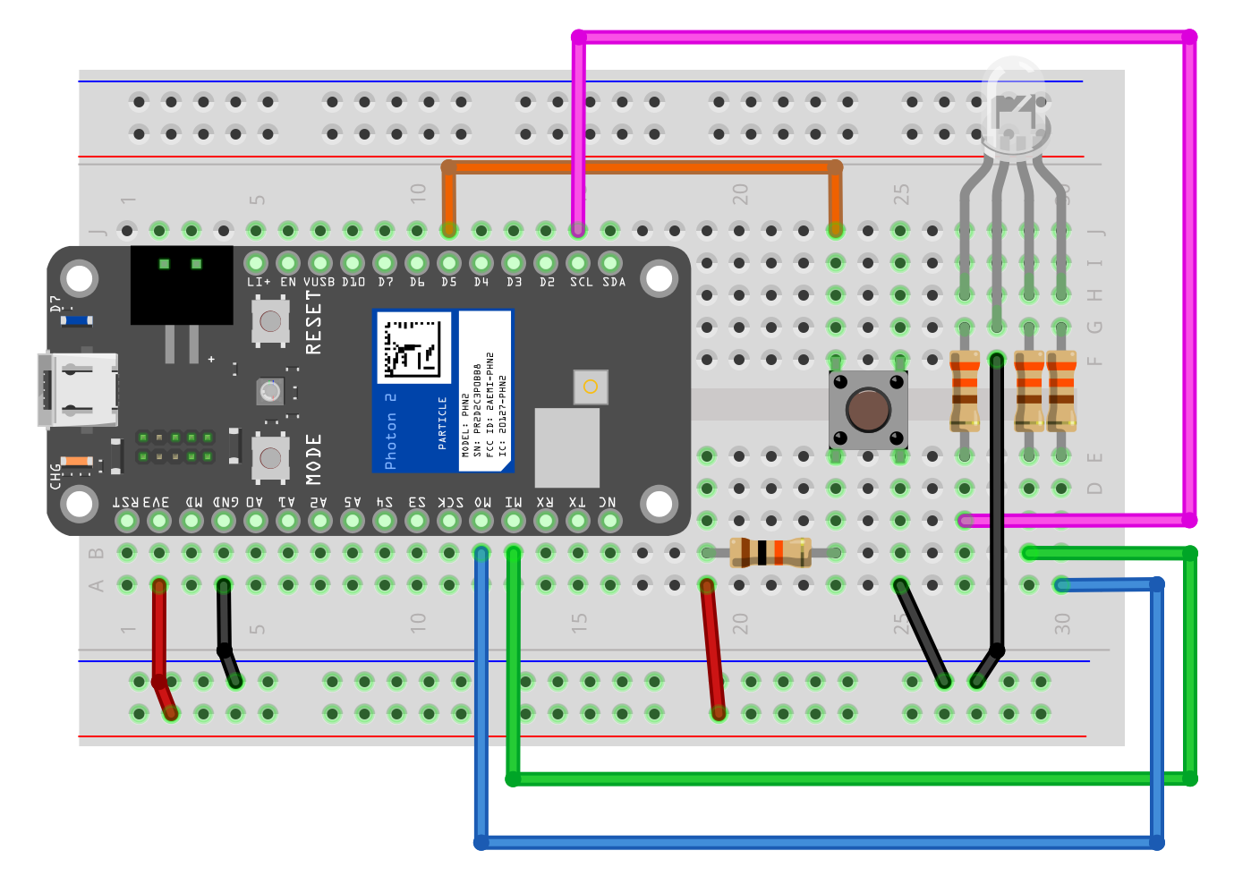
- Turn on red LED on only while button pressed
- Toggle red LED on and off after each time button is pressed
- Generate 1 new random color each time button is pressed
- Make each button press move LED through a sequence of colors
Credit