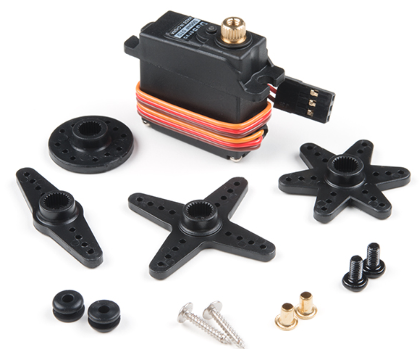
(Reference) Servo Motors
Servo Motors

Wiring Diagram

Wiring Guide
| Servo Wire | Photon 2 |
|---|---|
| Power | VUSB |
| Ground | GND |
| Signal | Any PWM-capable pin |
- Important: Most servos will require 5V not 3.3V so use
VUSB - If you want to use a servo with a LiPo battery, see these instructions
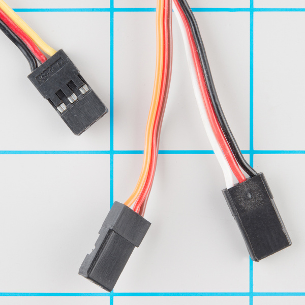
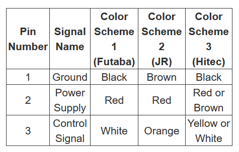
Notes on Servo Wire Colors
- The wiring colors vary with different servos so look carefully at your documentation


Operation
- Servo rotates 180 degrees based on input
- Use
Servoclass to allow you to send rotation values directly to servo - It is recommended to rotate from 15 degrees to 165 degrees (instead of 0-180) to protect the servo from damage
Code
const int SERVO_PIN = A2;

Servo servoObj;	// step 1: Create the servo object
void setup(){
    // step 2: attach the servo object to the servo pin
    servoObj.attach(SERVO_PIN);
}

void loop(){
    // step 3: write PWM values to servo pin

    servoObj.write(15); //write the servo to position 15 degrees
    delay(1000); //wait one second
    servoObj.write(90); //write the servo to position 90 degrees
    delay(1000);
    servoObj.write(165); //write servo to position 165 degrees
    delay(1000);
}
Jitting
- In some cases, the servo may start to make noise, stutter, or become hot when not it use
- This can be due to a variety of factors such as unstable current supply or interrupts in the Photon 2 execution
- IF this happens, one simple solution is to
attachbefore using the servo, and thendetachafter
Code: Fixing Jittering
const int SERVO_PIN = A2;
Servo servoObj;
void setup(){ /*no attach code */ }
}
void loop(){
    servoObj.attach(SERVO_PIN);
    servoObj.write(15); //write the servo to position 15 degrees
    delay(1000); //wait one second
    servoObj.write(90); //write the servo to position 90 degrees
    servoObj.detach();
}
Reminder: Photon 2 PWM Pins
- Only certain pins support PWM
D1(SCLorA4)A2A5MISO(D16)MOSI(D15)