(Reference) RGB LEDs
RGB LEDs
Pins

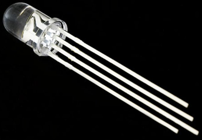
- RGB LEDs have four pins
- Three pins to each of R, G, B (shorter pins)
- One pin serves as either common anode or common cathode (longer pin)
Wiring (Common Cathode)

- R, G, B pins are anode (positive)
- Connect cathode (longer pin) to Ground (negative)
-
These are physically the opposite of regular LEDs
- Regular LED: anode is longer pin
- Common cathode RGB LED: cathode is longer pin
Operation
Digital Write
- Each LED color is either on or off
- Output
HIGHto anode turns that LED color on - Output
LOWto anode turns that LED color off
Analog Write
- Use pulse width modulation
- Each LED color can have a brightness level that varies from
0to255 - You can blend LEDs to create many different colors
- Only certain pins support PWM
D1(SCLorA4)A2A5MISO(D16)MOSI(D15)
Color Mixing
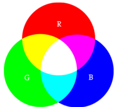
- Check out https://htmlcolorcodes.com/ to see how R, G, and B mix to create colors

Code
const int PIN_RED = D1;
const int PIN_GREEN = MISO;
const int PIN_BLUE = MOSI;

void setup() {
  pinMode(PIN_RED, OUTPUT);
  pinMode(PIN_BLUE, OUTPUT);
  pinMode(PIN_GREEN, OUTPUT);
}

void loop() {
  //digital write - White (R + G + B)
  digitalWrite(PIN_RED, HIGH);
  digitalWrite(PIN_GREEN, HIGH);
  digitalWrite(PIN_BLUE, HIGH);
  delay(1000);

  //digital write - Magenta (R + B)
  digitalWrite(PIN_RED, HIGH);
  digitalWrite(PIN_GREEN, LOW);
  digitalWrite(PIN_BLUE, HIGH);
  delay(1000);

  //analog write - White (R 255 + G 255 + B 255)
  analogWrite(PIN_RED, 255);
  analogWrite(PIN_GREEN, 255);
  analogWrite(PIN_BLUE, 255);
  delay(1000);

  //analog write - Orange (R 255 + G 165 + B 0)
  analogWrite(PIN_RED, 255);
  analogWrite(PIN_GREEN, 165);
  analogWrite(PIN_BLUE, 0);
  delay(1000);
}
Credit
- CC BY-SA 3.0, Source
- Sparkfun
- Images created with Fritzing