OLED Screens (old SPI version)
OLED Screens and SPI Communication
Note: Old Version with SPI
- The following describes the SPI version of the OLED screen
- This OLED is no longer used in our class
- Please see the I2C version of the OLED screen
ITP 348 - Introduction to Physical Computing
Learning Objectives
- Explain what synchronous, serial communication means
- Understand key concepts behind SPI protocol
- Identify OLED configuration parameters by reading through datasheet and software library
- Implement OLED screen in a device
Improving Output
-
Serial monitor is fine for debugging, but we need better output to build a device
-
Let’s introduce one output device
Introducing Organic Light-Emitting Diodes
OLEDs
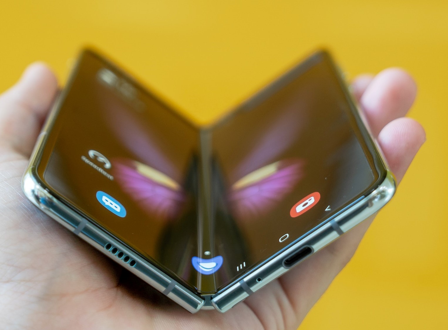 OLEDs are more complex than regular LEDs and be manufactured to be thin and bendable
- OLEDs are used in high end TVs, monitors, and phones
- OLEDs are more expensive than regular LEDs
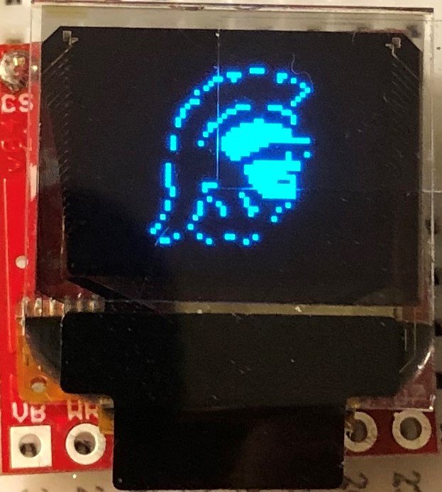
Our Micro OLED has two components
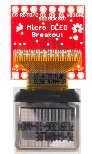
OLED screen

- Blue text on black screen
- 64 pixels (H) x 48 pixels (W)
- Operates at 3.3v
- Controlled via I2C or SPI protocol (more on this later)
- 31 pins (!)
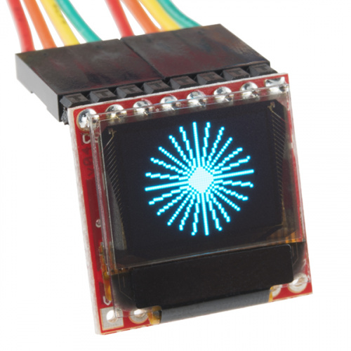
Breakout Board
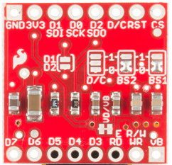
- Custom circuit board that provides access to (“breaks out”) the very delicate small pins on the screen
- This breakout board allows us to connect up to 16 pins, but we only need to worry about the top 8 pins
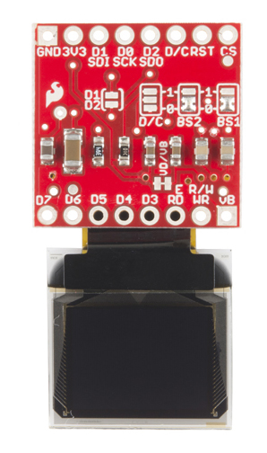
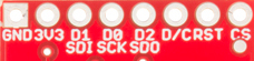
Breakout Board Pins
##
| OLED | SPI Function | Notes |
|---|---|---|
| GND | Ground | Ground |
| 3V3 | Power | 3.3v |
| D1 (SDI) | MOSI | Serial data in |
| D0 (SCK) | SCK | SPI clock |
| D2 (SDO) | MISO | Unused |
| D/C | Data / Command | Specify incoming byte as command or screen data |
| RST | Reset | Active-low reset (3.3v to enable) |
| CS | CS | SPI chip select (active-low) |
</span>
Communication
- Communicating with the screen directly is complicated but we can use a library to simplify
- This is similar to installing software on your computer to communicate with your printer (software driver)
- Photon 2 can communicate with the screen using two different protocols: SPI or I2C
- We will discuss I2C later in the course
What is Synchronous Communication?
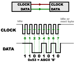
Synchronous Communication
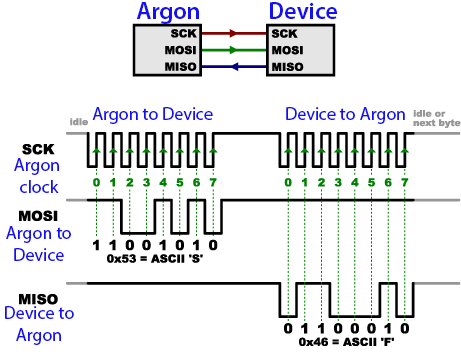
- Clock pin and data pin(s)
- Clock is an oscillating square wave
- Receiver reads data signal on clock rising edge (low to high)
- Synchronous: data sent on regular intervals controlled by a clock
- Serial: one bit at time is sent / received
What is Serial Peripheral Interface (SPI)?
- SPI is one implementation of serial synchronous communication to send and receive data between devices
- Synchronous: data is sent on regular intervals controlled by a clock
- Serial: one bit at time is sent / received
- Terminology:
- Photon 2 will be called main
- OLED (peripheral) will be called secondary
SPI Structure
SPI Structure
- Two data pins for bidirectional communication (one for sending data, one for receiving)
- Data from Photon 2 (Main Out) to OLED (Secondary In) is the MOSI pin
- Data to Photon 2 (Main In) from OLED (Secondary Out) is the MISO pin
Additional Pins
- SPI also includes a CS (chip select) pin, which is used to specify which secondary device is active
- e.g. if you were controlling multiple OLED screens
- OLED screen includes a D/C pin to distiguish between commands (e.g. clear screen) and data (e.g. display byte
01001011)
Photon 2 - OLED Screen Pin Mapping
see next slide ##
| OLED | Photon 2 | SPI Function | Notes |
|---|---|---|---|
| GND | GND | Ground | Ground |
| 3V3 | 3V3 | Power | 3.3v |
| D1 (SDI) | MO | MOSI | Serial data in |
| D0 (SCK) | SCK | SCK | SPI clock |
| D2 (SDO) | - | MISO | Unused |
| D/C | Digital Pin | Data / Command | Specify incoming byte as command or screen data |
| RST | Digital Pin | Reset | Active-low reset (3.3v to enable) |
| CS | Digital Pin | CS | SPI chip select (active-low) |
</span>
OLED Library
- We need a library to handle much of the complex communication with the OLED
- To install a library, go to the command palette and type
Install Library - Install the OLED library:
SparkFunMicroOLED
Lab
- Connect OLED and install library
- Use:
D/C (pin D5),RST (pin D6),CS (pin D7)
- Use:
- Run sample code; Modify sample code to display
Hello world! - Finally, create an Etch A Sketch using the OLED screen with two potentiometers (to draw) and one button (to reset)
- Library code
- Library guide
- Datasheet
Lab - Etch-a-Sketch

Credit
- Photo by Sparkfun
- Photo by Sparkfun
- Images created with Fritzing
- Photo by Mika Baumeister on Unsplash