DC Motors
DC Motors
Goals
-
Discuss the different types of motors used in small electronic devices
-
Introduce DC motors
-
DC motor power considerations
-
DC motor applications
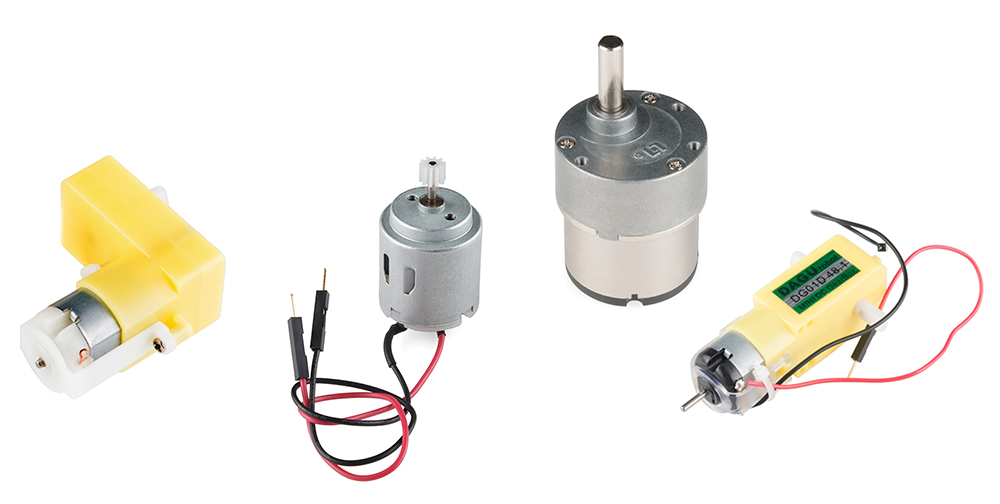
DC Motor Applications
- Hobby motors
- Small electronics
- Low-torque applications
- Large DC motors
- Electric scooters
- High-torque applications
- Motors can also generate electricity (generators / alternators)
How Do Brushed Motors Work?
- Electromagnetism!
- VERY brief physics aside
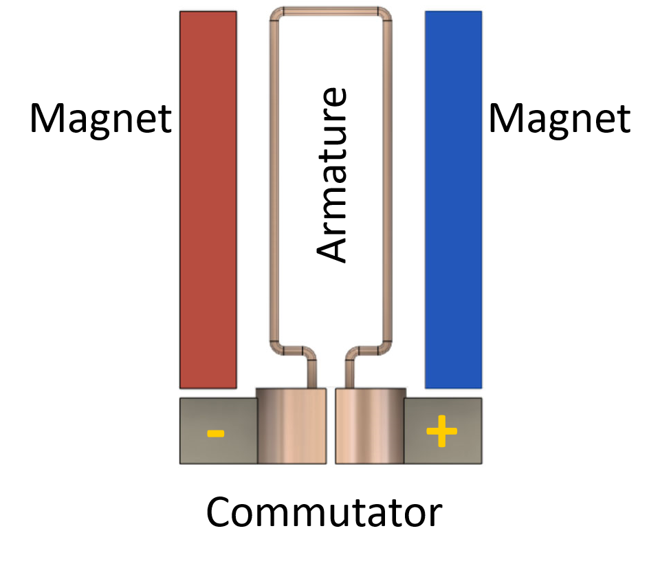
Electromagnetism
-
The guiding principle behind electric motors is the Lorentz Force
- Electrical current in a magnetic field produces a physical force
- Force direction is given by the “right-hand rule”
- Current direction along your index
- Magnetic field along your middle
- Force direction is along your thumb
Three Main Parts of DC Motor
- Stator magnets (stationary)
- Armature / Windings (rotating wire)
- Commutator (supplies current to armature)
Inside Simple DC Motor
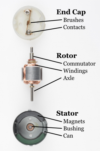
DC Motor Construction
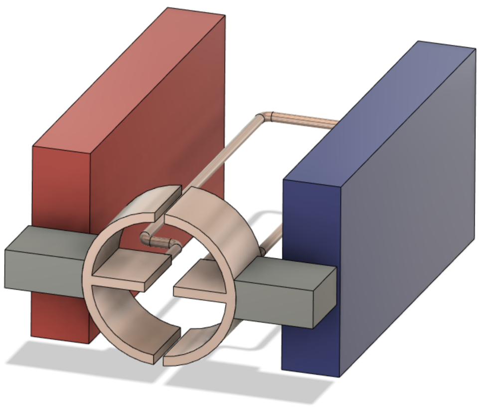
Illustration
DC Motor Types
| Brushed | Brushless (synchronous or electronically commutated motor) |
|---|---|
| Physical contact points in the commutator to switch current direction | Inverter to electrically switches the DC power supply to AC power supply |
| Pro: Relatively inexpensive | Pro: Less wear on moving parts |
| Con: Parts wear out over time | Con: More expensive |
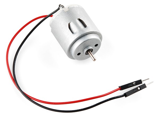
Exercise
- Attach fan blade to motor
- Connect red wire on motor to 3v3; connect black wire to ground
- What happens?
- Reverse the wires
- What happens?
- Was the speed the same in either case?
Motors
- Spin is controlled by current direction
- If direction is reversed, the motor spins in the opposite direction
- It is not practical to have to reverse the wires to change motor direction
- Also, we have no way to control speed
Motor Controller
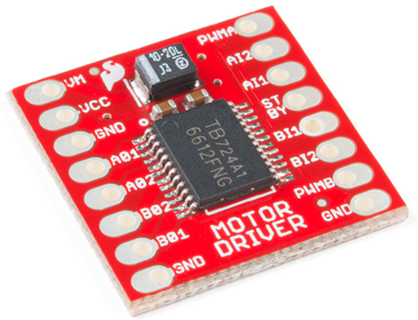
Motor Driver
- Motor (motor controller) provide greater control over motors
- Motor drivers don’t give a (+) or (-) connection
- Just have an IN1 or IN2 because we can change polarity
- Motor drivers also provide circuit protection
- Motor drivers can control two different motors independently
Motor Controller Wiring Guide
| Motor Controller | Explanation |
|---|---|
| PWMA | Motor A speed (PWM) |
| AI1, AI2 | Motor A direction control (connect to Photon 2) |
| AO1, AO2 | Motor A output (connect to motor) |
| PWMB, BI1, BI2, BO1, BO2 | Controls for motor B |
| VCC | Power for chip (3v3) |
| VM | Power for motors (3v3, or higher for powerful motors) |
| STBY | Enable motor (3v3) |
| GND | Ground |
</span>
Controlling the Motor Direction
- Setting the direction is done by changing the two input pins to HIGH and LOW separatel
- Ex:
AI1 = HIGHandAI2 = LOWis one direction - Ex:
AI1 = LOWandAI2 = HIGHis other direction
- Ex:
- Setting them both to LOW means stopping the motor
- Setting them both to HIGH can damage the motor
Controlling the Motor Speed
- The PWM method of controlling motor speed operates on this range: [0-255]
- Typically the PWM must be somewhat greater than 0 before it starts to spin
- Reminder: only certain pins support PWM
D1(SCLorA4)A2A5MISO(D16)MOSI(D15)
Wiring Diagram

Wiring Guide
| Motor Controller | Photon 2 |
|---|---|
| PWMA | A5 |
| AI2 | D4 |
| AI1 | D3 |
| AO1 | Motor wire (either) |
| AO2 | Motor wire (either) |
| VCC | 3v3 |
| GND | GND |
| VM | 3v3 |
| STBY | 3v3 |
Exercise
- Attach the fan blade to the DC motor
- The theoretical PWM values are 0 to 255. Write a sketch to determine the min and max values.
- Write a sketch that powers up the fan from the practical minimum (the value we established in the previous exercise) to the maximum
- There should be a ramp up in speed, getting progressively faster until it maxes out