Pulse Width Modulation
Pulse Width Modulation
Analog Output
- Goal
- Produce analog outputs (e.g. make an LED half as bright, rather than off or on)
- Problem
- Photon 2 does not have analog outputs (and neither do many microcontrollers)
- Solution
- We will fake it!
Pulse Width Modulation (PWM)
- PWM is a technique we use to simulate analog outputs
- Basically, we switch a digital ouput on/off very quickly (modulate)
- Also specify how long the output is on, and how long it is off (pulse width)
- The result is the “effective” output voltage can be varied (since the signal is switching between high and low)
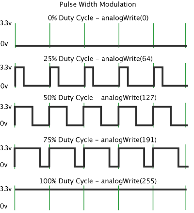
Key Terms
- Square wave: a digital output that switches repeatedly from high (3.3v) to low (0v)
- Pulse width: how long the signal is high (usually in milliseconds)
- Duty cycle: percentage of one “cycle” that a signal is at 3.3v
- Period: time for one on/off cycle to complete (usually in milliseconds)
- Frequency: how many times per second the on/off cycle repeats (Hz) (default Photon 2 PWM frequency is 500 Hz or 2 ms)
Key Terms Illustrated
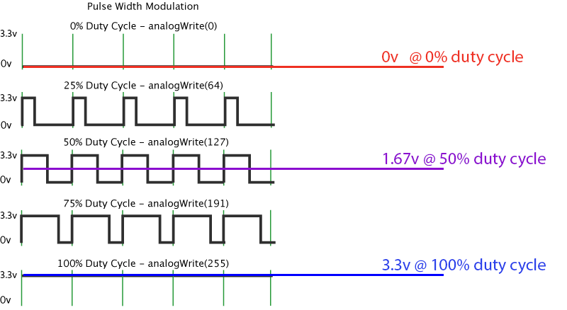
Questions
- What is the output voltage of an Photon 2 pin?
- What is the effective output voltage using PWM with 50% duty cycle?
- What is the effective output voltage using PWM with 25% duty cycle?
- What is the effective output voltage using PWM with 0% duty cycle?
Why does this work?
Using PWM
- Only certain pins support PWM
D1(SCLorA4)*A2A5MISO(D16)*MOSI(D15)*
- PWM pins can have different PWM values (duty cycles), but must share the same frequency and resolution.
*You can use any of these pins labels.
##
Writing Analog Output with analogWrite
Syntax
analogWrite(PIN_NUMBER, VALUE);
//VALUE: 0-255
- You can control the pulse width with
VALUE - We discussed duty cycle as 0%-100%, but
VALUEis 0-255- Why?
Example
analogWrite(LED_PIN, 127);	//50% duty cycle, or 1.67v

analogWrite(LED_PIN, 192);	//75% duty cycle, or 2.45v

analogWrite(LED_PIN, 0);	//0% duty cycle, or 0v
Wiring Diagram
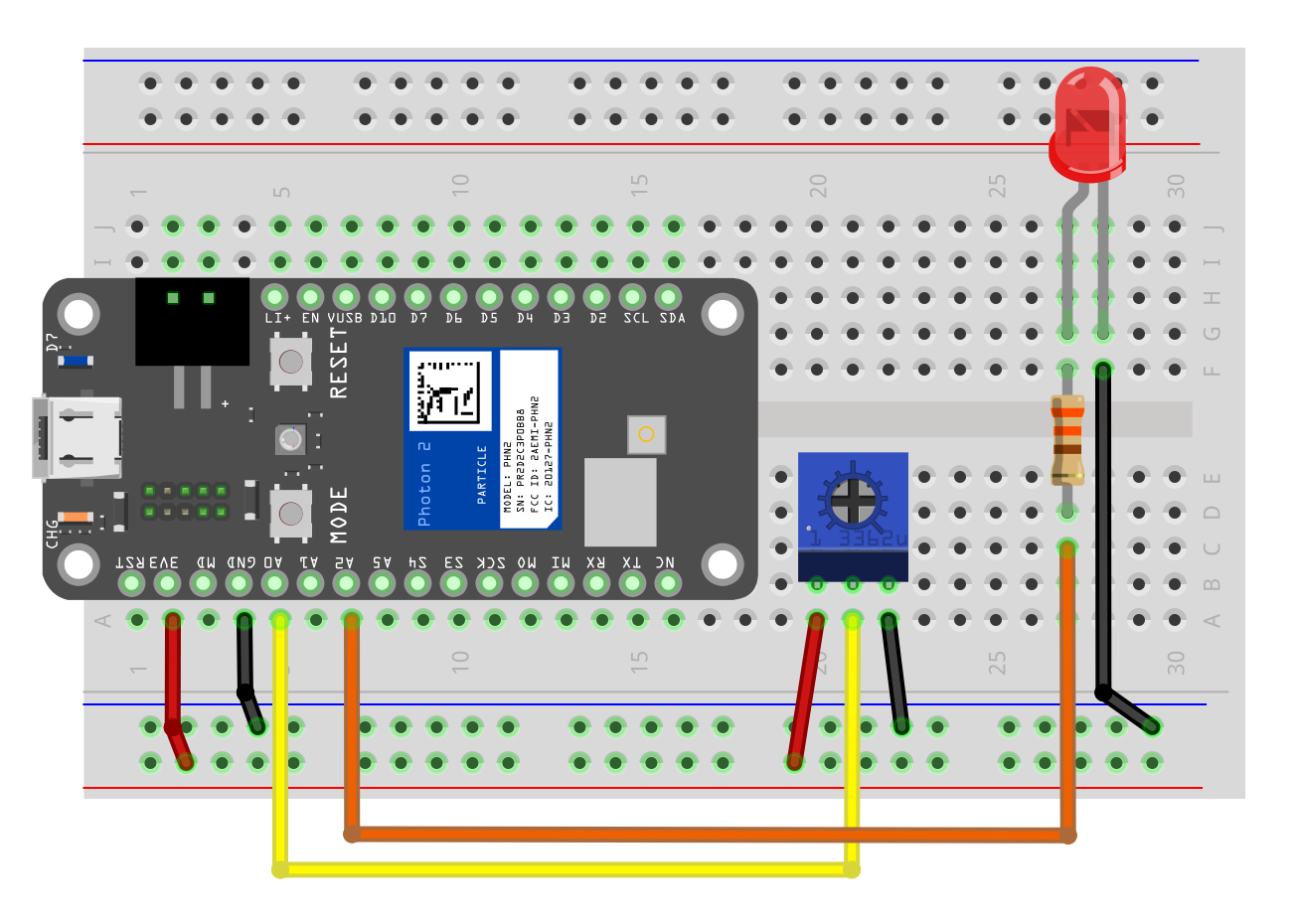