Analog Input with Potentiometers
Analog Input
Plan
- Analog vs. digital
- Potentiometer
- Voltage dividers
- Reading analog input
Analog vs. Digital

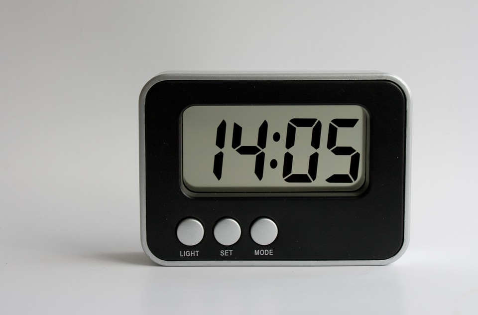
Analog vs. Digital
| Analog | Digital |
|---|---|
 |
 |
| infinite variations / states | discrete (or finite) states |
Potentiometer (Pot)
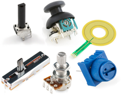
- Variable resistor with 3 pins
- power, ground, wiper
Potentiometer (Pot)

- Wiper pin connects to circuit
- As wiper moves, resistance varies from 0 Ohms to max (e.g. our kit has 10K Ohms pots)
Where do we find pots?
Where do we find pots?

- Also car stereo knobs, dimming light switches, etc.
How a Potentiometer Works
How a Potentiometer Works

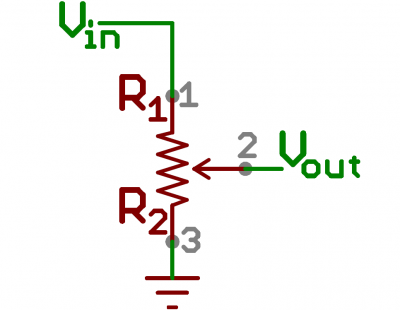
- Vout is the wiper (middle pin; connects to Photon 2 analog input)
- Inside the potentiometer is a resistor
- As the knob moves, the wiper divides the resistor, and the ratio of resistance between Vin-and-Wiper and Wiper-and-Gnd varies
- This is called a variable voltage divider (more on this later)
Question

- With a 10K Ohm pot, if the wiper is exactly halfway, what is the resistance between Vout and Gnd?
Voltage Dividers

- Photon 2 input pins can measure voltage, not resistance
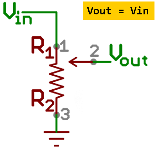
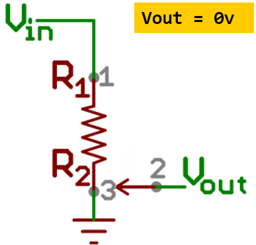
- By connecting Vin (3.3v), Gnd, and Vout (wiper), we can now vary the voltage difference Vin-and-Wiper and Wiper-and-Gnd
Voltage Dividers

- If the wiper is exactly halfway, what is the voltage between Vout and Gnd?
- If the wiper is all the way to the top, what is the voltage between Vout and Gnd?
Voltage Divider
- As those resistances changes, so does the voltage difference between Vin-and-Vout and Vout-and-Gnd
- This is known as a voltage divider
Setting up Analog Input
Syntax
const int PIN_POT = A0;		//input pin
int potValue = 0;			//value from read

void setup() {
    pinMode(PIN_POT, INPUT);
}
- Pins A0-A5 are analog input
- Technically, analog pins are input by default but I like to do this for clarity and consistency
Reading Analog Input
Syntax
void loop() {
    potValue = analogRead(PIN_POT);
}
Wiring Diagram

- Using Vin=3.3v and a 10k potentiometer, what do you expect for the range of values of potValue?