LEDs and Digital Output
LEDs - Light Emitting Diodes
LEDs
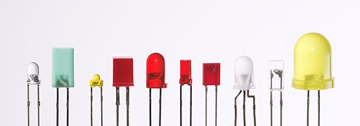
- Light emitting diodes are basically small light bulbs (but use significantly less power)
- LEDs are everywhere!
- (Nearly) all the blinking lights around us (e.g. router, washing machine, etc.)
- Smartphone flash
- TV remotes (infrared LEDs)
- Energy-efficient light bulbs
- Some displays
How LEDs Work
How LEDs Work
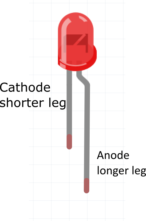
- Light emitting diode is made of two layers of semiconducting material
- When the voltage at the anode (longer leg) is about 2.2v more than the voltage at the cathode (shorter leg), the LED emits light
- This positive voltage difference is called forward biasing
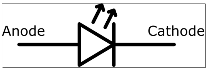
LEDs are Directional (aka Have Polarity)
- LEDs allow current to flow in only one direction
- If positive voltage is applied to the anode, light will emit
- If positive voltage is applied to the cathode, light will not emit (aka the polarity is reversed)
LED Precautions
- LEDs have limitation in how much current they can handle
- More current = brighter light …up to a point, and then the LED breaks
- This is why we use a resistor to limit the flow of current
- We call this a current limiting resistor
- The resistor can be before or after the LED in the circuit
Exercise
- What do you think will be the difference between using 10KOhm resistor vs 330 Ohm resistor?
LED Datasheet
- Datasheet
- Forward Current
- Peak Forward Current
- Forward Voltage
Choosing a Current-Limiting Resistor
- Rule of Thumb: 330 Ohms or 220 Ohms are common options
- For this class, go ahead and use whichever is available
- Why?
Let’s turn on LED without any Code
- We can “hardwire” an LED to turn on by connecting the anode (long side) to a +3.3V and the cathode (short side) to ground
- The LED is always on because the anode is always at +3.3V and the cathode is always at ground
Turning on LEDs in Code
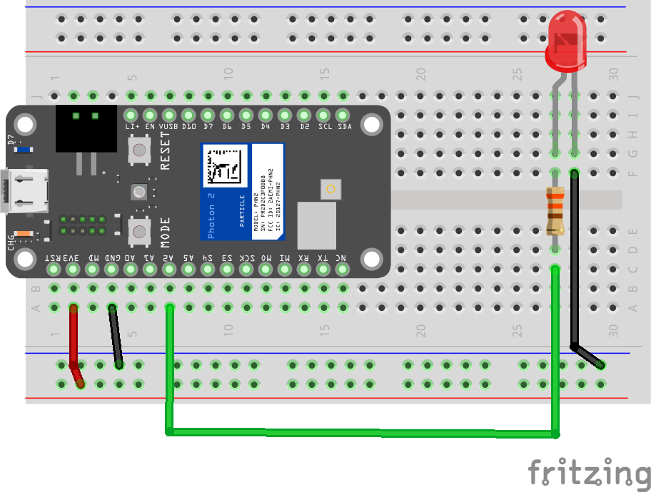
- We need to be able to control the voltage at the anode so it can be either +3.3V (LED turns on), or GND (LED turns off)
- Connected anode to pin D2 on Photon 2
- Connected cathode to GND
- Now using code, we can make the voltage at pin D2 either +3.3V or GND
Wiring
Digital Output
- These are signals that are HIGH or LOW
- HIGH is 5V (pin
VUSB) or 3.3V (pin3v3)- HIGH is considered “true”
- LOW / false is 0V (ground)
- LOW is considered “false”
- HIGH is 5V (pin
Setting input / output with pinMode
Syntax
pinMode(PIN_NUMBER, MODE);
//MODE: OUTPUT or INPUT
- Before we can use pins on the Photon 2, we need to specify if pins will be used for input or output
- Most pins on the Photon 2 can be configured to SEND output (e.g. to turn on a light) or to RECEIVE input (e.g. a button press)
- When you want to use a pin in your program, you should specify its mode in
setup()
Writing Digital Output with digitalWrite
Syntax
digitalWrite(PIN_NUMBER, VALUE);
//VALUE: HIGH or LOW
- You can send an ON (HIGH) or OFF (LOW) signal at output on a pin
- This is writing a digital value
- Digital values are like boolean values: 0/1, on/off, true/false
Credits
- Afrank99 - Own work, CC BY-SA 2.0, Link
- CC BY-SA 3.0, Link
- Images created with Fritzing