Photoresistors
Measuring Light with Photoresistors
Learning Objectives
- Describe what a photoresistor measures and what it is used for
- Understand voltage divider concept behind photoresistor operation
- Implement a device using photoresistor
- Calibrate photoresistor with appropriate values in firmware
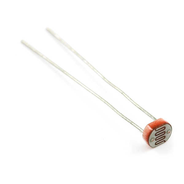
Photoresistors
- Measures light levels
- Contains a photosensitive variable resistor
- Changes in light level causes a change in resistance
- Also called photocells or photodetectors
Notes about Photoresistors
| Useful for | Not Useful for |
|---|---|
| Detect relative change in light level | Detecting absolute light level |
| Knowing when to brighten / darken a display screen screen (e.g. phone) | Comparing light level across different devices and sensors |
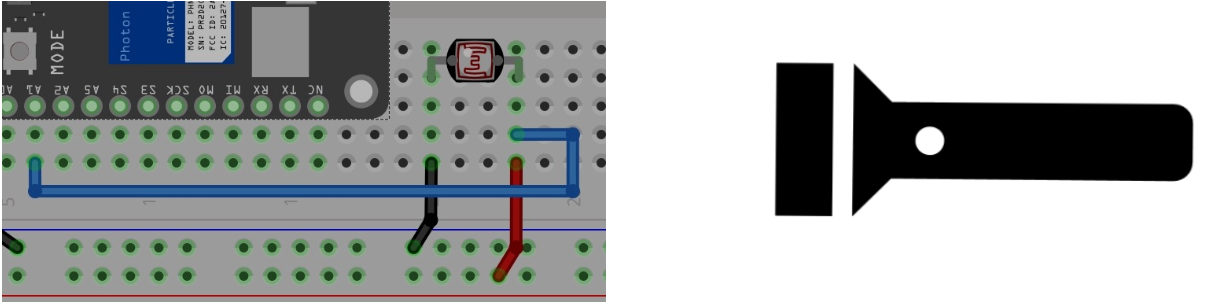
Wiring a Photoresistor
- Consider wiring a photo resistor to 3.3v and ground
- Measure voltage
- The resistance will vary with light, but what is the problem?
What happens in bright light?
- Bright light –> resistance decreases
- Analog input reads 3.3v
What happens in darkness?
- Darkness –> resistance increases
- Analog input still reads 3.3v
- ?
Why is this happening?
Review: Potentiometers
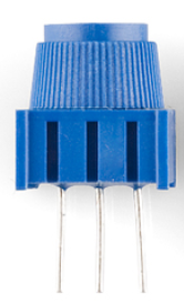
- A potentiometer is also a variable resistor (like a photoresistor).
- When the potentiometer’s resistance varied, we were able to “see” (read) a voltage change (unlike with the photoresistor)
- Why was that?
- Could we use a similar approach?
Review
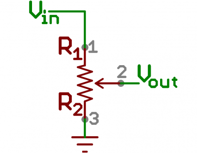
- Potentiometers have 3 pins: 3.3v, GND, and a wiper can move across a fixed resistor
- Vout represents the voltage at wiper
- As the knob moves the wiper across the resistor, the ratio of resistance between Vin-and-Vout and Vout-and-Gnd varies
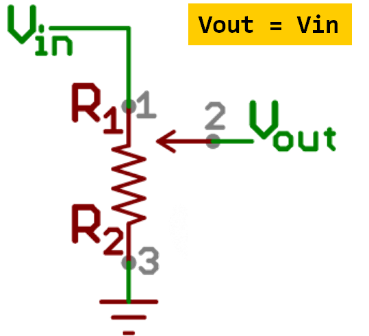
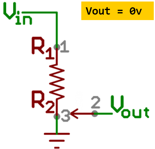
Review
- As those resistances changes, so does the voltage difference between Vin-and-Vout and Vout-and-Gnd
- This is known as a voltage divider
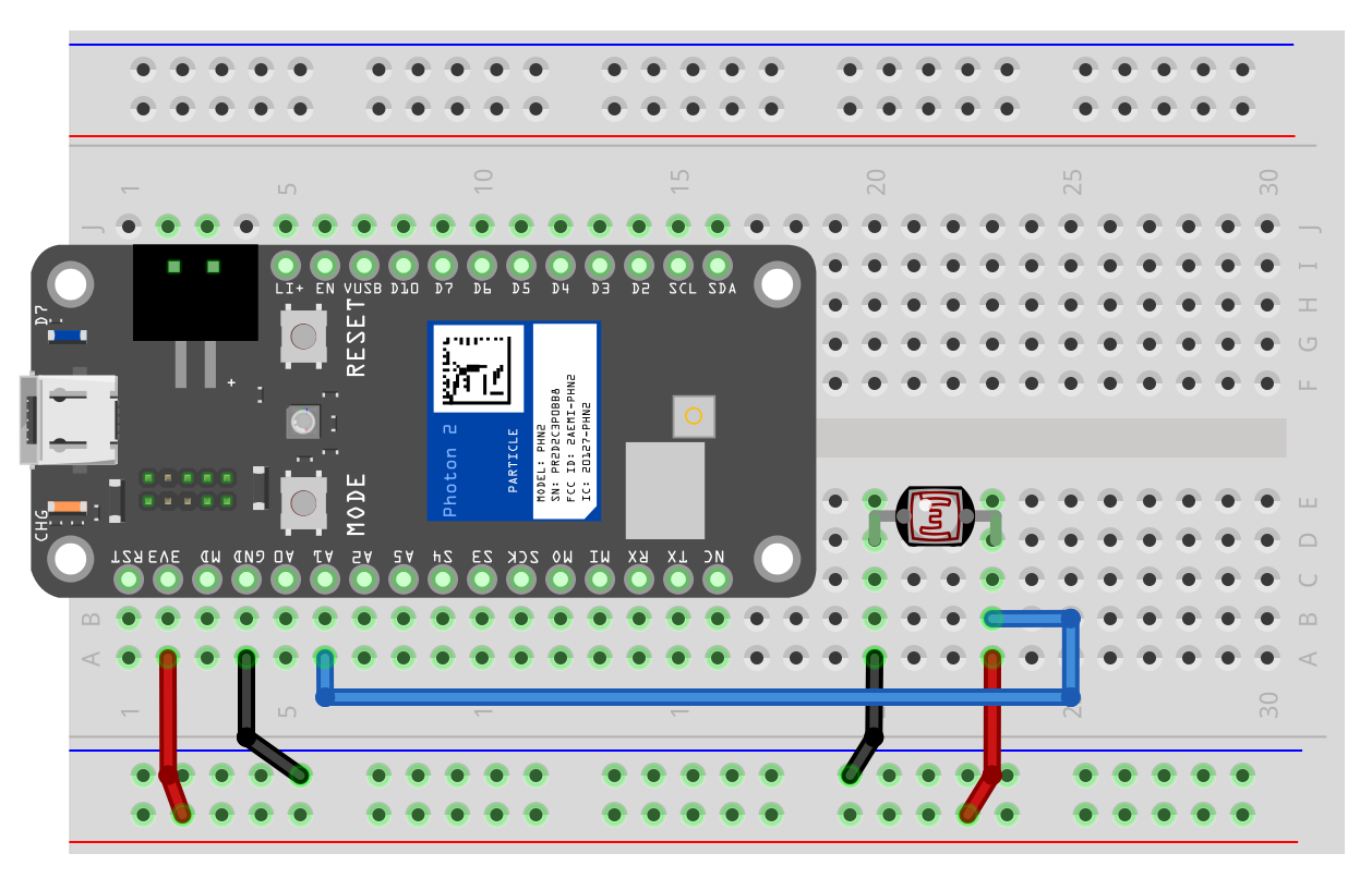
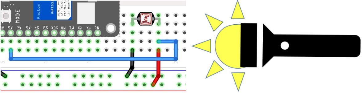
Photoresistor solution
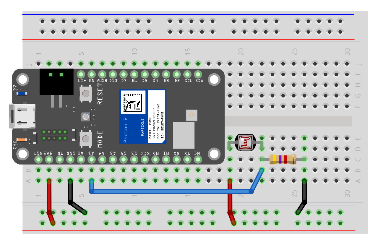
Photoresistor solution
- Use a fixed resistor (usually 4.7k*) in series with photoresistor
- Connect one end of photoresistor to 3.3v, and the end to the resistor
- Connect the other end of the resistor to ground
- Use the Photon 2 to measure the voltage in the middle
* 4.7k is not a magic value. It a reasonably good value for normal lighting conditions
Exercise
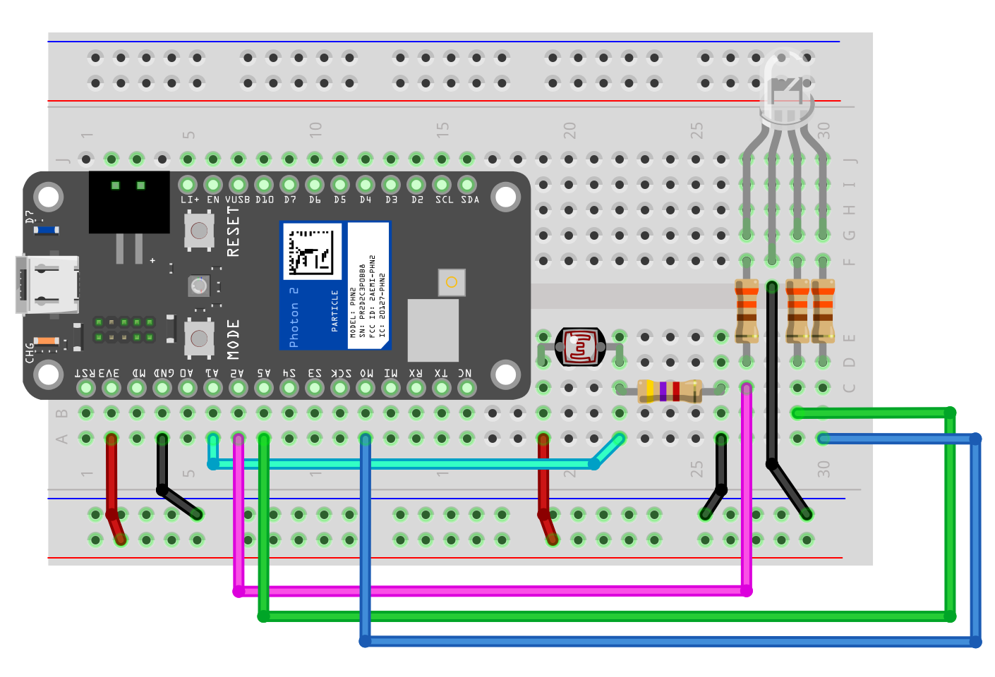
Lab (with breakout groups)
- Read and display the value from between the photoresistor and resistor.
- Measure it based on different lighting conditions: normal room light, covering the sensor with your hand, shining
- Part 1:
- Display on the serial monitor if you room light dark, light, or ambient
- Display a different LED color based on the light states
- Hint: how will you determine what type of light is present?
- Part 2:
- Set the LED to specific color
- Use the values from the photoresistor to control the brightness of the LED. For example, use PWM to brighten / darken the light based on the photoresistor values. You will need to convert / scale the photoresistor values to the PWM values